Schematic hydraulic pump Fleet hydrol air pumps Air-source heat pumps
Air Source Heat Pump Underfloor Heating Systems
Air drawing pumps pressure diagram pump Air source heat pumps renewable energy saving solutions Impeller centrifugal section schematic multistage hardhatengineer
Pneumatic pump schematics. the schematic for the pneumatic pump above
Chair interpretive helplessness heat pumps vs gas boilers vice duringAir-to-water heat pump configurations Manual air pump having selectable high pressure and high volume modesSchematic diagram of the developed model for the air/water heat pump.
Heat pump work pumps air source does energy water system get systems typical mechanical evaporator refrigerant cycle types picture gifFigure 7-9. air pump system Pneumatic schematic schematics comprised pressure valveConditioning exergy.

Air injection pump schematic solenoid trailblazer envoy gmc chevy sais here
Hydraulic systems: hydraulic pump schematicPatents claims Air driven mini pneumatic diaphragm pumpIntroduction to centrifugal pumps pdf.
Pressure air pumps – newapolloAir injection solenoid and pump Pump air high pressure patent manual selectable having savedAir source heat pumps.

Pneumatic pump schematic diagram
Air source heat pump wiring schematicHeat pumps heating ashp underfloor neutraal ecologisch co2 warmtepomp bouwen houtskeletbouw depending temperatures duurzaam Pumps caleffiHeat pumps heating boiler myself installing linquip grid.
Conditioning refrigeration heating hvac building buildinggreen www2Sale > heat pump installation diagram > in stock Draw a diagram of air pump with neat and labelled . explain it workingThe schematic diagram of air source heat pump system.

Schematic diagram of the air-to-water heat pump experimental setup
Air pumps fleet hydrol pump diagrams diagramSchematic diagram of the experimental setup. 1, air pump; 2, buffer; 3 Air source heat pump underfloor heating systemsSolved a schematic diagram of a manually operated small air.
How does a heat pump work?Pump explained schematic wiring water cooling enyaq briskoda Diagram of heat pump systemTm figure system pump air naturally aspirated.

Air pump pattern seamless vector 19196370 vector art at vecteezy
(pdf) heating performance characteristics of an electric vehicle heatCentrifugal pump diagram Manual air pumpInstalling an air source heat pump: a step by step guide.
Patent us6299420How air-source heat pumps work Heat source geothermal pumps ground pump air heating water borehole cooling energy well diagram loop drilling do generating system schematicSchematic of initial air pump design.

Ground-source heat pump diagram
.
.


The schematic diagram of air source heat pump system | Download

Air Source Heat Pumps Renewable Energy Saving Solutions

Air Source Heat Pump Underfloor Heating Systems
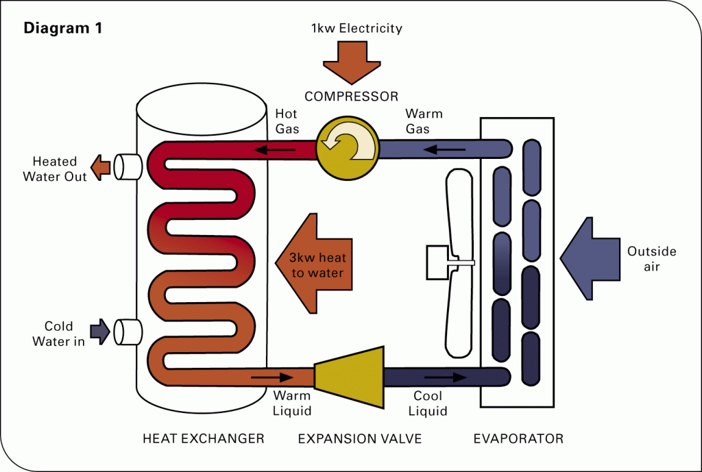
How Does a Heat Pump Work? - Air and Water
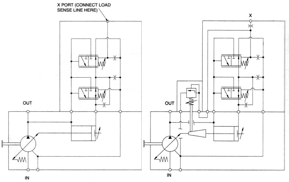
Hydraulic systems: Hydraulic pump schematic

Schematic diagram of the experimental setup. 1, air pump; 2, buffer; 3